Akai 27" TV Repair, LCT2785TA - Akai 32" TV Repair LCT3201AD - Will Not Power On
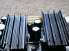
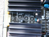
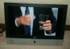
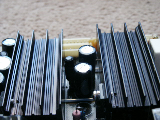
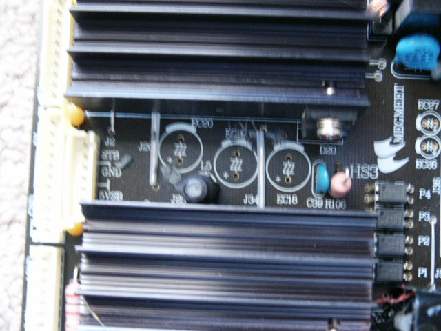
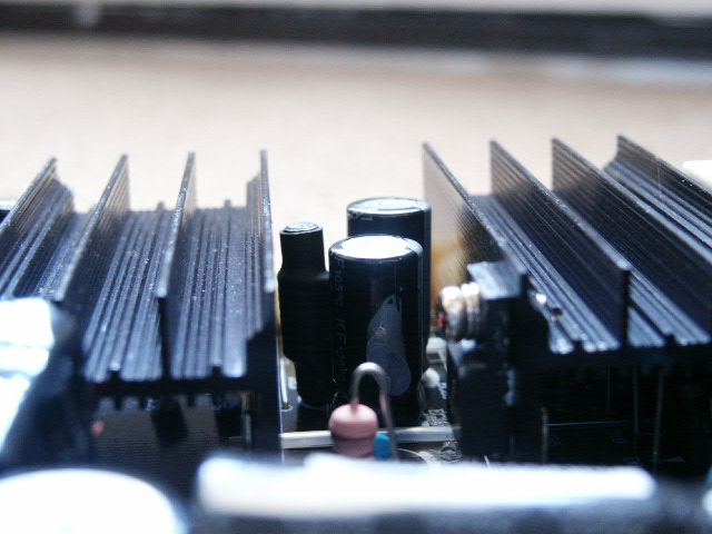
A friend of mine had not one but two Akai flat panel HD TV sets that would not power on. The power button on the back was on so there was a red standby light lit on the front of the set. However, when he pressed the power button, the red light would turn green for about 5 seconds then go back to red. On one of the sets, it would come on if he unplugged it then plugged it back in. Turns out there are a few capacitors bad on the power control board. I don't know anything about capacitors, or what they do but I watched a few video's on www.YouTube.com that claim you you visually inspect them and tell if they are bad. Basically if they don't look nice and new, they are likely bad. The easiest way to tell if you have a bad capacitor is the top of it will bulge. So, I pulled the back off the sets and seen a few that looked bad. A few were bulged, one or two had discoloration on them and one looked a little rusty so I replaced all of the ones that were bad.
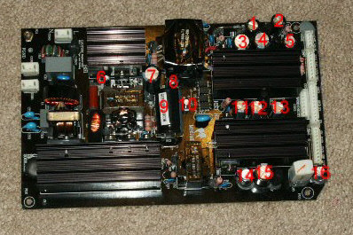
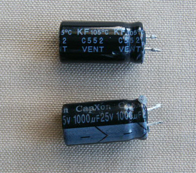
Some people order several capacitors and just replace as many as they can, I just replaced the ones that looked bad. On both sets there were three in a row that were damaged so I replaced those three on both sets and one or two others on each set. The three that were bulging were 1000uf 16v 105º capacitors. It's real important to get high quality capacitors that have a high temperature rating. Most of the capacitors that you find at Radio Shack will be lower temperature capacitors that probably wont last long at all. So order a few good capacitors and hopefully you wont have to repeat the job in a few years. I read where one person installed capacitors that had higher volt ratings, instead of 16v they installed 25v. I do not recommend that but it worked for them.
The job took about 2 hours. It was kinda a mess because I decided to remove the back of the set, order the capacitors I needed, then put the machine back together. So I had to have the set placed where it could sit apart for a week. I will list the capacitors that I found on the board and you can order a few of each or just check first like I did. One person recommended replacing all of the capacitors. To me that would be like replacing all the light bulbs in your house because a few blew out. Your call.
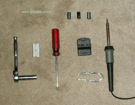
Tools Needed:
| Capacitors, at least the main three that seem to always be blown. | Cross tip screw driver, #2. |
| Razor or real sharp knife. | Flash light. |
| Thin soldier. | Soldering iron. |
| Screw layout page. | Ratchet wrench or large screw driver to remove wall mount bracket. (optional). |
| Hot glue gun (optional). | Puffer (optional) |
Capacitors for Akai LCT2785TA
|
|
|
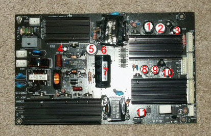
Capacitors for Akai CLT3201AD
|
|
|
Warning: The TV operates on HIGH VOLTAGE and there is a huge risk of electrical shock. The power board can store power so care should be taken when working around it. I recommend that you unplug the TV for no less than 1 day prior to messing with the power control board. What I actually did was unplugged the machine and made several attempts to turn it on with the standby button. I was trying to bleed off any stored power. Not sure if that helped but I am still alive so I do not think it hurt.
Instructions:
-
Unplug the TV set.
-
Try to turn the TV set on with it unplugged.
-
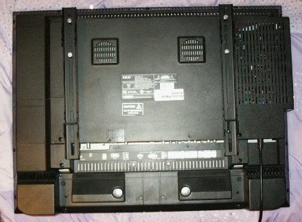
Take the set off the wall or mount and lay it flat on a firm flat smooth sturdy surface that it can sit safely on for several hours.
NOTE: The TV display panel is very sensitive and can easily be damage. I set on set on a firm bed and the other on a carpeted floor. Find a place where it will not get damaged/broken.
-
Set the screw layout page where you can place the screws on it. This makes it easier to put the screws back in the set.
-
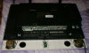
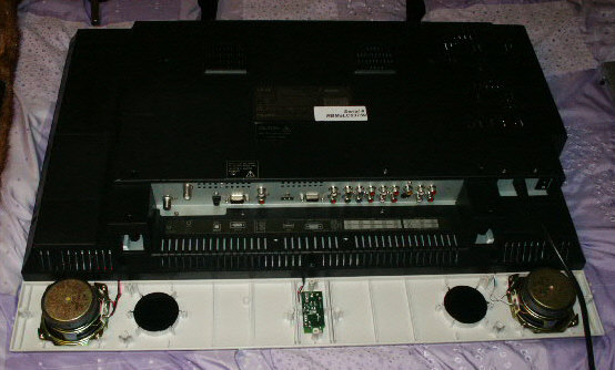
Remove the screws from the lower part of the back of the set. The lower panel covers the speakers, etc.. 6 Screws.
-
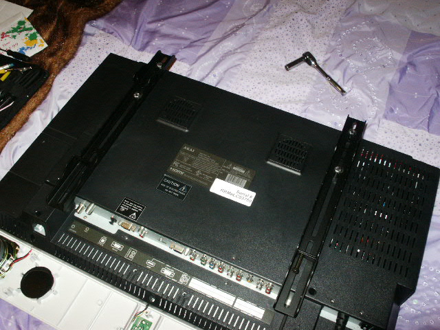
Remove the wall mount bracket if installed.
-
Remove the pedestal if installed.
-
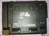
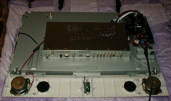
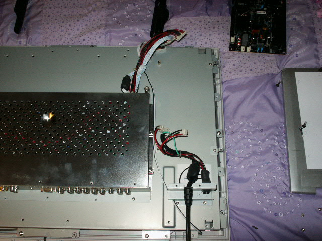
Remove the main back panel. There were several screws of different sizes.
NOTE: Carefully remove the back panel from the set. While doing so, you will need to thread the plug through the back panel.
-
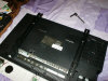
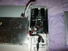
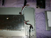
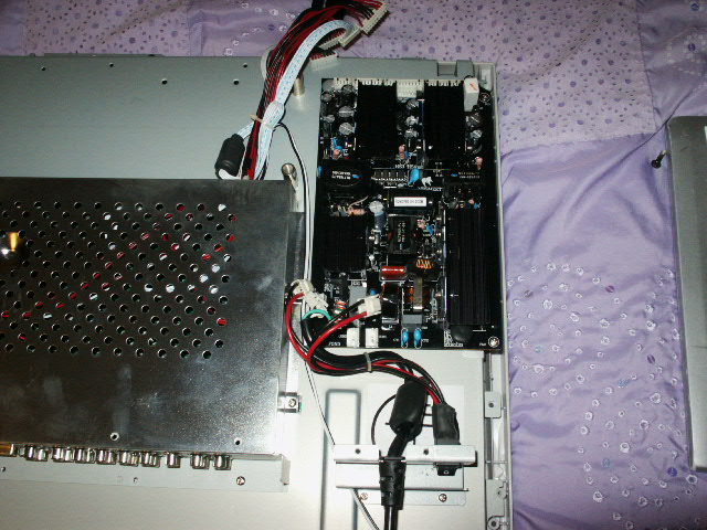
Once you have the back off, you will see the power control board. Inspect the board to see if you can identify any bad capacitors. If none look bad or damaged, you may want to stop there and take the set to a shop. If you do see capacitors that look damaged, identify them and order the parts you need.
NOTE: Do not remove capacitors until you have the new ones to install. They have to be install in the proper polarity and it is harder to mix that up if you remove them when you are ready to replace them.

-
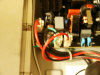
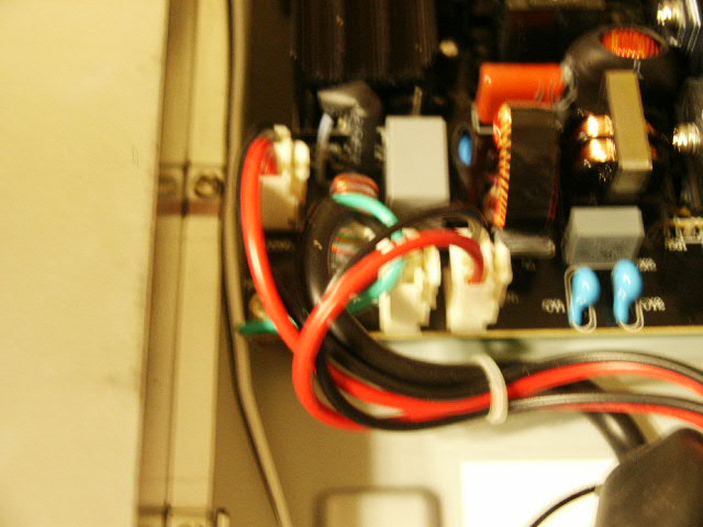
Unplug the power cord from the control board. It will have a slide on plug(s) and a screwed on ground wire near the bottom of the board.
NOTE: Take not where the plugs connect. The plugs in will likely have glue on it. I used a razor sharp knife to cut the glue before I pulled the plug loose. I did not want to risk cracking of damaging the board by trying to pull the plug loose without first cutting the glue loose.
-
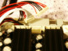
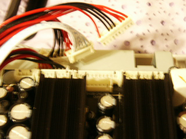
Cut the glue on the top wire connectors and unplug those connectors. The set I was working on had 5 connector strips. There were all different pin sizes so I was not worried about getting them mixed up.
NOTE: Be careful not to damage the wire connectors or board connections when you remove these wires.
-
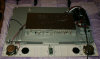
Once all the wires are disconnected from the power control board, unscrew the board from the back of the set. Has 3 screws besides the 1 screw that holds the power cord ground wire on.
-
Take the solder iron and remove the bad capacitors. Heat 1 connection at a time and work the capacitor out.
NOTE: The capacitors have a + side and a - side. The - side is clearly marked on the edge of the capacitor. There is also a + mark on the board so you have a good chance installing them with the correct polarity. They to install them as you removed them.
-
Once a capacitor is out, clean out the hold in the board so you can get the other capacitor in easy. What I did was heat the old solider on the lower side of the board with the tip of the iron and when pulling the solider iron away from the board I blew in the top side of the hole so the melted solider cleared the hole. You could also use a puffer to vacuum the old solider out of the hole once it is heated.
-
Place the new capacitor in the hole and solider it in place one post at a time.

-
When you have all of the capacitors replaced, re-assemble the TV set from step 14 backwards.
NOTE: I did NOT use a glue gun to secure the connectors to the board. I think the glue was used to secure the wires to the board because there was a good chance they would come loose because the wires were new and had not taken their current shape in the set. I could be wrong, your call. -
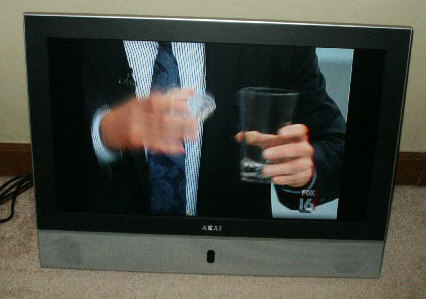
Once the set is back together, test it to make sure it works. If it does not, there is likely some other problem with the set.
Please leave a donation, see the bottom of this page.
End of instructions.